- 您现在的位置:买卖IC网 > Sheet目录370 > ZXLD1320DCATC (Diodes Inc)IC LED DRVR WHITE BCKLGT 14-TDFN
�� �
�
�ZXLD1320�
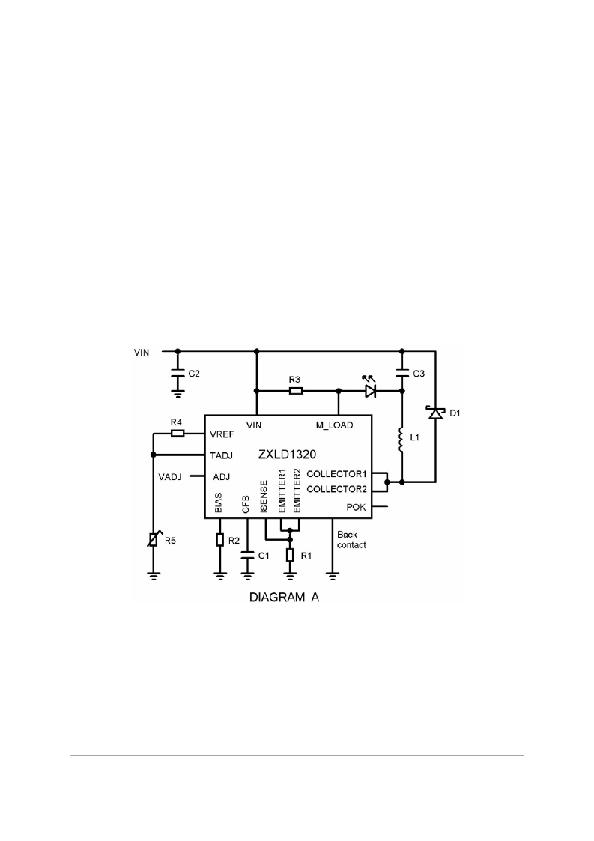
�Typical� operating� conditions�
�Inductive� converters� can� operate� in� either� CONTINUOUS� mode,� where� current� always� flows� in�
�the� inductor,� but� rises� during� the� ON� period� and� falls� during� the� OFF� period,� or� DISCONTINUOUS�
�mode,� where� the� current� falls� to� zero� during� the� OFF� period.� The� mode� depends� on� several�
�factors,� including� supply� voltage,� output� (LED)� voltage� and� the� choice� of� peak� current� and�
�inductor� value.� Calculations� need� to� be� done� to� determine� which� mode� the� converter� will� be� in.�
�The� circuit� should� be� designed� to� give� slightly� more� LED� current� than� required� under� the� lowest�
�supply� voltage,� so� the� control� loop� can� regulate� the� current� accurately.� If� the� theoretical� LED�
�current� is� less� than� that� required,� the� control� loop� will� not� be� able� to� reach� the� required� value.� The�
�calculations� will� give� an� idea� of� the� ON� and� OFF� times� and� hence� the� operating� frequency,� but�
�bear� in� mind� that� the� control� loop� will� reduce� the� peak� current� to� achieve� the� exact� programmed�
�LED� current� and� this� will� raise� the� operating� frequency.� In� general,� values� in� the� discontinuous�
�mode� are� simpler� to� calculate� because� the� current� can� go� from� zero� to� the� theoretical� maximum�
�during� the� ON� period� and� fall� to� zero� during� the� OFF� period.� In� continuous� mode� the� current� will�
�start� from� some� value,� so� the� ON� time� will� be� lower� to� reach� the� theoretical� maximum� and� lower�
�still� when� the� control� loop� reduces� the� peak� current� below� the� maximum.�
�Circuit� operation�
�Operation� of� a� buck� LED� driver�
�Used� when� the� input� voltage� is� higher� than� the� LED� voltage,� this� circuit� has� an� ON� phase,� where�
�the� LED(s)� and� coil� are� connected� in� series� from� the� supply� to� ground� and� an� OFF� phase,� where�
�the� coil� current� circulates� through� the� LED� via� a� Schottky� diode.� Thus� current� flows� in� the� LED(s)�
�during� the� ON� phase� and� during� at� least� part� of� the� OFF� phase.�
�ADJ� is� set� between� 50mV� and� 500mV� to� give� between� 10%� and� 100%� power� respectively.� Making�
�R2� =� ZERO� gives� a� base� current� to� the� output� transistor� of� 50mA� nominal� and� making� R2� =� 1.68k� Ω�
�gives� 10mA� nominal.� The� reduced� base� current� will� lower� supply� current� and� hence� improve�
�efficiency� in� lower� power� applications.� Making� R1� =� 33m� Ω� gives� a� peak� coil� current� of� 1.5� Amps.�
�The� internal� power� transistor� turns� on� until� the� coil� current� builds� up� to� the� peak� value,� this�
�Issue� 1� -� January� 2008�
�?� Zetex� Semiconductors� plc� 2008�
�14�
�www.zetex.com�
�发布紧急采购,3分钟左右您将得到回复。
相关PDF资料
ZXLD1321DCATC
IC LED DRVR WHITE BCKLGT 14-TDFN
ZXLD1322DCCTC
IC LED DRIVR WHITE BCKLGT 14-DFN
ZXLD1350ET5TA
IC LED DRIVR WHITE BCKLGT TSOT-5
ZXLD1352ET5TA
IC LED DRIVER HIGH BRIGHT TSOT-5
ZXLD1356DACTC
IC LED DRIVER WHITE BCKLGT 6-DFN
ZXLD1360ET5TA
IC LED DRIVR WHITE BCKLGT TSOT-5
ZXLD1362ET5TA
IC LED DRIVR WHITE BCKLGT TSOT-5
ZXLD1366DACTC
IC LED DRIVER WHITE BCKLGT 6-DFN
相关代理商/技术参数
ZXLD1321
制造商:ZETEX 制造商全称:ZETEX 功能描述:Boost mode DC-DC converter for LED driving with 1A output and current control
ZXLD1321DCATC
功能描述:直流/直流开关转换器 DC-DC Boost Conv 1A output RoHS:否 制造商:STMicroelectronics 最大输入电压:4.5 V 开关频率:1.5 MHz 输出电压:4.6 V 输出电流:250 mA 输出端数量:2 最大工作温度:+ 85 C 安装风格:SMD/SMT
ZXLD1322
制造商:DIODES 制造商全称:Diodes Incorporated 功能描述:BUCK/BOOST MODE DC-DC CONVERTER
ZXLD1322DCCTC
功能描述:直流/直流开关转换器 Buck-Boost DC-DC Con 0.7A output RoHS:否 制造商:STMicroelectronics 最大输入电压:4.5 V 开关频率:1.5 MHz 输出电压:4.6 V 输出电流:250 mA 输出端数量:2 最大工作温度:+ 85 C 安装风格:SMD/SMT
ZXLD1322DCCTC-CUT TAPE
制造商:DIODES 功能描述:ZXLD1322 Series 15 V 600 kHz 700 mA Buck/Boost Mode DC-DC Converter - DFN-14
ZXLD1322DCTC
制造商:ZETEX 制造商全称:ZETEX 功能描述:Buck/boost mode DC-DC converter for LED driving with 700mA output and current control
ZXLD1350
制造商:ZETEX 制造商全称:ZETEX 功能描述:350mA LED driver with internal switch
ZXLD1350_07
制造商:ZETEX 制造商全称:ZETEX 功能描述:350mA LED driver with internal switch